CME Initiation, Evolution, and Interplanetary Consequences
HAO scientists have carried out 3D isothermal MHD simulations of the evolution of the large scale coronal magnetic field as a twisted magnetic flux tube is driven (slowly) through the lower boundary into a pre-existing coronal arcade field.
MHD SIMULATIONS OF CME INITIATION AND DYNAMIC EVOLUTION
It is found that depending on how rapidly the ambient coronal magnetic field declines with height, the emerging flux rope may lose confinement and erupt through either the onset of the torus instability or the kink instability (Figure 1). In the former case the erupting flux rope primarily shows an outward expansion while in the latter case the flux rope develops significant writhing or rotation. Both types of eruptive behavior have been observed. (Fan & Gibson, 2007.)
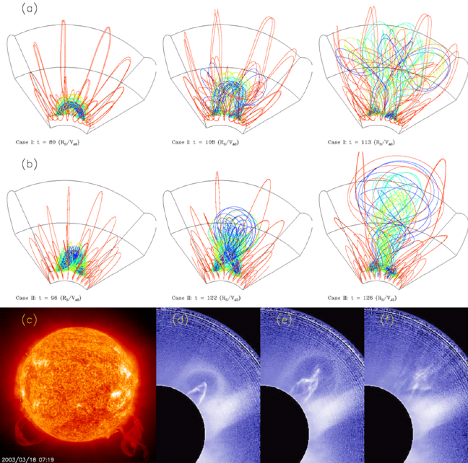
Figure 1. (a) and (b) show two MHD simulations of the eruption of a twisted flux rope in the coronal triggered by the onset of the torus instability and the kink instability respectively. (c) shows an image observed by SoHO EIT in He II emission at 304 Angstrom of two large solar prominences erupting nearly simultaneously at the two limbs, one showing mainly outward expansion and the other showing significant rotation, similar to the two types of eruptions modeled by the simulations. (d)(e)(f) show snapshots of a CME that began at 01:30 UT on Feb 18 2003 observed by HAO's MLSO MK4 in white light, where the core prominence of the CME shows significant kinking motion.
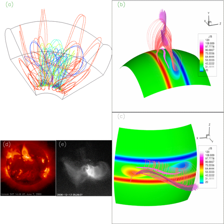
Figure 2. (a) shows a snapshot of the 3D coronal magnetic field of an erupting flux rope due to the onset of the torus instability; (b)(c) show respectively two perspective views of the current sheet (as delineated by the iso-surface of J/B), a set of post-reconnection loops (red field lines), and also field lines of the 'bald-patch separatrix surface' (pink field lines), which are dipped field lines grazing the lower boundary at the polarity inversion line, remaining underneath the post-reconnection loops, determined from the magnetic field shown in (a); (d)(e) show respectively Yohkoh and Hinode X-ray images of two eruptive flares, where both events show a configuration of X-ray post-flare loops straddling some underlying sigmoid loops.
Both cases found formation of a current sheet of sigmoid morphology prior to the onset of the eruption. The current sheet intensifies during the eruption and reconnections in the current sheet produce post-reconnection loops with cusp-shaped tops. Some sigmoid shaped dipped fields are found to remain beneath the post-reconnection loops during the early phase of the eruption in both cases (Figure 2). These results explain the observed presence of X-ray sigmoids in CME source regions, and the transition from X-ray sigmoid brightening to cusp-shaped post-flare X-ray loops, which in some cases are seen to straddle a remaining under-lying X-ray sigmoid, during an eruption.
CONNECTION TO MAGNETIC CLOUDS
Connecting interplanetary coronal mass ejections (ICMEs) to their coronal pre-eruption source requires a clear understanding of how that source may have evolved during eruption. Gibson and Fan (2006a, 2006b) presented a three-dimensional MHD simulation of the eruption of a kinked flux rope, which showed how, in the course of eruption, a coronal flux rope may writhe and reconnect both internally and with surrounding fields in a manner that leads to a partial ejection of only part of the rope as a CME. Gibson and Fan (2008) explicitly determined how such evolution during eruption would lead to alterations of the magnetic connectivity, helicity, orientation, and topology of the ejected portion of the rope so that it differs significantly from that of the pre-eruption rope. These changes complicate how ICMEs embedded in the solar wind relate to their solar source. In particular, the location and evolution of transient coronal holes (Figure 3), topology of magnetic clouds ("tethered spheromak") (Figure 4), and likelihood of interacting ICMEs would differ significantly from what would be predicted for a CME which did not undergo writhing and partial ejection during eruption.
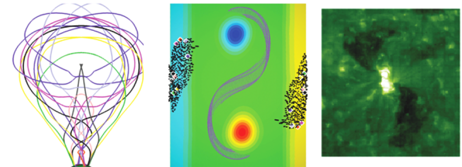
Figure 3. From Gibson and Fan (2008). Transient coronal holes (TCHs) are associated with CMEs, and appear as dimmings in soft X-ray and extreme ultraviolet (e.g. right-most image). They have been proposed to be the footpoints of expanding magnetic flux ropes. The left-most image shows sample field lines from the escaping portion of the flux rope in the Gibson and Fan (2006a, 2006b) simulation. The middle image shows colored diamonds corresponding to the footpoints of these escaping rope fieldlines, and the black dots show more footpoints of escaping rope fieldlines obtained by tracing all fieldlines exiting the top of the simulation box (10 Rsun) down to the lower boundary. The central purple fieldlines show the surviving rope as seen in projection against the solar surface, which is illustrated by colored iso-contours showing radial magnetic flux. The model predicts that the escaping flux rope footpoints lie outside the original (and surviving) rope's boundary, which compares well to the observations of the SOHO/EIT 195 transient coronal holes of May 12, 1997 that is shown in the right-most image.
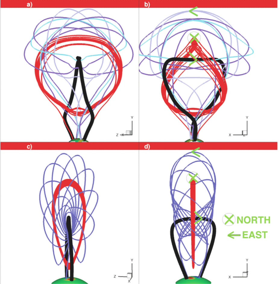
Figure 4. From Gibson and Fan (2008). Model predictions of magnetic fields within magnetic clouds (interplanetary manifestations of CMEs). The top images show sample field lines of the escaping portion of a partially-ejected flux rope, which we demonstrate is topologically equivalent to a "tethered spheromak" described in the analytic model of Gibson and Low (1998) (bottom images). The thick black field lines in (a-b) and (c-d) represent the poloidalaxes of the partially-ejected rope and tethered spheromak, respectively. The red torus shown in (c-d) is formed by a single field line ergodically covering a magnetic flux surface which encloses the spheromak toroidal axis. The partially-ejected rope possesses a similarly toroidally-winding single red field line, although it is not completely detached from the lower boundary.