Heliographic Coordinate Tool
Download software (zip file, contains software and user instructions)
Download instructions only (PDF)
The NCAR High Altitude Observatory (HAO) IDL routine, ‘fvp_kcor_v2.pro’, allows a user to display, and save, heliographic coordinate positions of features in Mauna Loa K-Cor white light coronagraph fits images. The ‘Download Software’ file, ‘kcor-utilities-master.zip’, contains all the IDL routines needed to obtain and save the measurements, and a pdf file ‘KCor_heliographic_coord_info.pdf’ containing instructions and information about the program. A partial overview of the instructions are provided here.
When launching the program, include the filename of the K-Cor image on the command line:
IDL> fvp_kcor_v2,’ 20220918_175341_kcor_l2.fts’
The program displays the image, and the user selects a point by moving the cursor to the desired location and clicking the left mouse button. The program will mark the point in the image with an ‘X’ and a ‘1’, as shown in Figure 1, to indicate this is the first point selected by the user. It also prints the heliographic position in solar radius and position angle in the IDL window. The location of point 1 is:
IDL> [x,y]: 803 796 [r,th]: 1.44 Rsun 327.26 degrees
Solar radius is measured from Sun center and the position angle (P.A.) is measured from solar north in the counterclockwise direction. Multiple points can be selected by moving the cursor and clicking the left mouse button. When done, click the middle mouse button to exit the program.
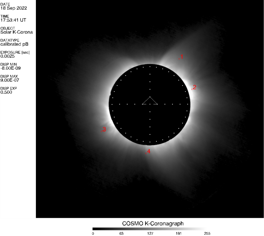
Figure 1: K-Cor polarization brightness image and selected points as displayed by fvp_kcor_v2.pro
It is often the case that the user will want to save both the measurements and the image with the marked locations. To save, use the Boolean keywords ‘/text’ and ‘/png’ when you start the program:
IDL> fvp_kcor_v2,’ 20220918_175341_kcor_l2.fts’, /text, /png
The /png keyword creates a png format image of the IDL window that includes the K-Cor image and the locations and designations of the measured points as shown in Figure 1. The /text keyword saves the measured positions in a .txt file. The.txt file contains the image file name, the x-y pixel and heliographic coordinates of the points measured. The text file for the measurements in Figure 1 is called ‘20220918_175341_kcor_l2_pos.txt’ and contains this information:
20220918_175341_kcor_l2.fts.gz Position Measurement[s]

Position # 1 [x,y] pixels: 803 796 radius: 1.44 P.A.: 327.26

Position # 2 [x,y] pixels: 860 659 radius: 1.18 P.A.: 289.70

Position # 3 [x,y] pixels: 455 470 radius: 1.47 P.A.: 119.30

Position # 4 [x,y] pixels: 654 371 radius: 1.31 P.A.: 175.46
where P.A. is the position angle.
Using K-Cor nrgf and subtraction images
The default intensity scaling is set to display a K-Cor polarization brightness [pB] image as illustrated in Figure 1. K-Cor high contrast images, i.e. normalized radially graded filter, ‘nrgf’ images (see Morgan et al. 2006), are better suited for measuring the positions of coronal features at heights above the very low corona (e.g. CMEs, helmet- and pseudo-streamers). The ‘nrgf’ normalization algorithm greatly increases the contrast by flattening the steep brightness gradient of the corona. Another type of K-Cor image is a subtraction image. K-Cor subtraction images are ideal for measuring dynamic structures such as CMEs. To set the proper default scaling for nrgf or subtraction images, use the Boolean keyword (/nrgf or /subt) on the command line as shown below:
nrgf:

IDL> fvp_kcor_v2,’20220918_175341_kcor_l2_nrgf.fts’,/text, /png, /nrgf

subtraction:

IDL> fvp_kcor_v2,’20220918_175341_kcor_minus_174334_good.fts’,/text, /png, /subt
The keyword will apply a default intensity scaling suitable for each image type.
Customize the intensity scaling
Coronal intensity values and contrast depend on the brightness of the coronal structures located near the solar limb. The brightness of coronal structures can vary significantly. The user may need to change the default image brightness and contrast by designating their own minimum (i.e. wmin) and maximum (i.e. wmax) display scaling and the exponent (i.e. wexp) applied to the data intensity. The default values of the variables used to scale the intensity for the different K-Cor data types are shown in Table 1.
| K-Cor Image Type | Default Values of Intensity Scaling Variables | ||
|---|---|---|---|
| wmin | wmax | wexp | |
| Polarization brightness (pB) | -8.e-9 | 9.e-7 | 0.5 |
| NRGF | -2.0 | 4.0 | 1.0 |
| Subtraction | -4.e-9 | 9.e-9 | 1.0 |
Polarization brightness (pB) and subtraction fits images are in calibrated coronal brightness relative to the brightness of the solar disk [i.e. B/Bsun]. Nrgf fits images are normalized contrast enhanced images and are in relative units. To improve the contrast, the user can provide their own values of wmin, wmax, and wexp on the command line.
Customized Scaling Example: K-Cor subtraction image of CME on Jun 10, 2021 18:21:48 UT
A K-Cor CME subtraction image from Jun 10, 2021 is used to measure the leading edge of the CME as shown in Figure 2. The default scaled image is shown on the left in the figure and user-provided scaling intensities are shown in the image on the right. The user-provided scaling significantly enhances the contrast of the CME in the outer field-of-view where intensities are typically fainter. The commands used in the two cases are:
Default scale:

IDL> fvp_kcor_v2,’20210610_182148_kcor_minus_181142_good.fts’,/text,/png, /subt

User Provided:

IDL> fvp_kcor_v2,’20210610_182148_kcor_minus_181142_good.fts’,/text,/png, wmin= -1.e-9, wmax=3.e-9, wexp=1.
Note: Do not use the ‘/subt’ keyword when providing your own intensity scale values. The default and user intensities applied to the images in Figure 2 are shown in Table 2.
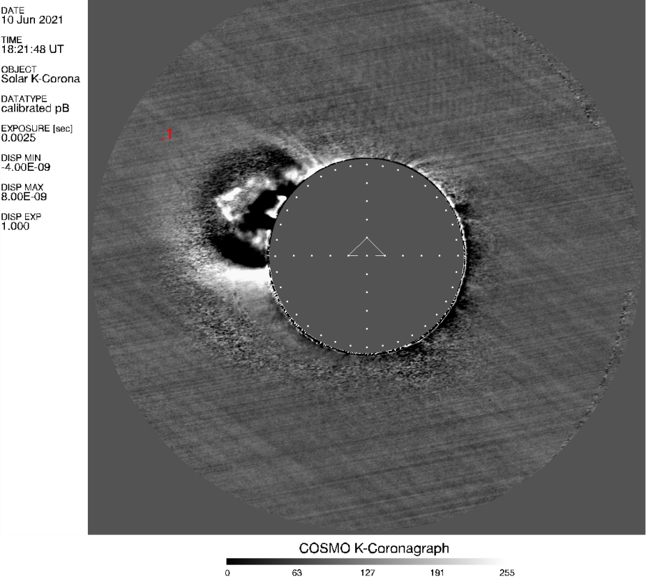
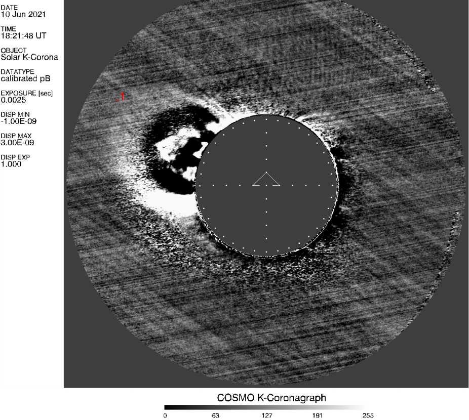
| Intensity Scaling | wmin | wmax | wexp |
|---|---|---|---|
| Subtraction Default | -4.e-9 | 9.e-9 | 1.0 |
| User Provided | -1.e-9 | 3.e-9 | 1.0 |
Additional Information
The complete instructions, ‘KCor_heliographic_coord_info.pdf’ [download at top of page] also contain an example of custom scaling using K-Cor nrgf images as well as a listing of all the routines in the software package and links to SolarSoft IDL.
User Help
If you have questions about the NCAR/HAO software or if you are having problems with the fvp_kcor_v2.pro routine, or problems accessing the K-Cor data from the Mauna Loa home page please email: mlso_data_requests@ucar.edu